What Bearings and Seals Do Inside a Gearbox Housing
Posted by zpgear zpgear
Filed in Other 0 views
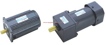
Walk through any machine builder's workshop and you will notice that many compact conveyors, mixers and lifting stages place the motor beside the load rather than behind it, which is exactly where a Right Angle Gear Motor earns its place, but how does it manage to turn the power through a corner so smoothly?
The secret lives inside the gearbox, where the motor's fast, light rotation meets a set of gears that change both its direction and its character. Most designs use either a worm and wheel pair or a bevel and helical arrangement. Open a spare housing on a bench and you will see the contrast at once: a worm looks like a fine screw, while bevel gears look like two small cones meeting at their tips.
A worm gear works by sliding rather than rolling. The threaded worm turns, its flank pushes against the teeth of the wheel, and the wheel advances a little with each rotation, which is why a single stage can achieve a large reduction in a small space. That sliding action creates some friction and warmth, and it also produces a quiet, even motion that many users find pleasant on a calm production line.
Bevel and helical combinations take a different route. The teeth are cut at an angle so that they engage gradually instead of striking all at once, and that gradual contact spreads the load and keeps the sound low. These stages tend to be more efficient than a worm, so they are a natural choice when a machine runs for long hours and the owner cares about energy use.
Gear ratio is the quiet hero of the whole arrangement. Reducing the speed raises the turning force at the output shaft in roughly the same proportion, which is how a small motor can move a heavy hatch or a loaded belt without straining. I once watched a modest unit lift a steel door that three people could barely shift, and the only sound was a low, patient hum.
Self locking is a feature unique to some worm designs. When the angle of the thread is shallow enough, the wheel cannot drive the worm backward, so a load held in the air stays where it is even when the power is off. That behavior is valuable on lifts and gates, although it should never replace a proper brake where safety rules demand one.
Shaft layout shapes how the gearbox joins the machine. A solid output shaft accepts a coupling, sprocket or pulley with a key, while a hollow shaft slides over the driven shaft and clamps on, which saves space and removes a coupling from the stack. Choosing between them is mostly a question of how the machine was drawn, and both rely on the same internal gearing.
Bearings and seals support the moving parts quietly. Tapered or deep groove bearings hold the shafts in line and carry the side loads that pulleys and chains create, while lip seals keep oil inside and dust outside. A faint film of oil around the output seal after a long shift is usually harmless, but a growing wet patch suggests the seal is tiring.
Lubrication ties everything together. Oil or grease forms a thin layer between the tooth surfaces, carrying heat away and reducing wear, and the mounting orientation decides how well that lubricant reaches each gear. Fitting a unit upside down compared with its design can starve certain bearings, so the manual's orientation notes deserve a careful read before the bolts go in.
Backlash, the tiny free play between meshing teeth, matters most when a machine reverses direction or must stop at a precise position. Well cut gears keep it small, and you can feel a trace of it by rocking the output shaft gently by hand with the motor off. If you want to compare how different housings, ratios and shaft options are arranged, the listings at https://www.zpgearmotor.com/product/ cover a wide range, and understanding these functions makes it far easier to judge what a Right Angle Gear Motor can realistically do on your own machine.